|
RAILWAY OPERATING DEPARTMENT |
|
|
Home |
|
|
| |
UNIVERSAL WORKS
IN
"FUNNY BUSINESS"
|
|
| |
|
|
| |
 |
|
| | | |
|
The redbrick architecture of Universal
Works - as originally built - allowed it to
represent just about anywhere in the World that
was industrialised in the 19th century while its modular construction
also permitted the close comparison of trains and aircraft.
However, with layout depth often being at a premium at model railway exhibitions and the Universal Works 2.0 rebuild
featuring a canal as a default boundary, the opportunity was taken to
build an optional full length - yet shallow - scenic module consisting of
an overgrown canal bank, pavement and road - ultimately lit with Peco Model Scene gas lamps.
Just as the "engineering works with airfield" format was ideal for a celebration of
English Electric, the presence of a canal and suitable road for vehicles offered scope for new challenges
such as this scenario prepared for the Cheltenham GWR Modeller's Exhibition
in April 2013:
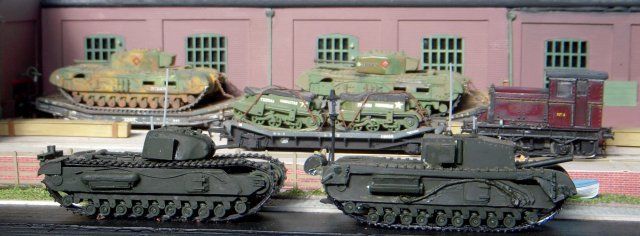
In the closing months of the Second
World War much of British industry was busy producing vehicles for the final
assault on Hitler's Festung Europa. Universal Works had specialised in
repairing gun tanks and modifying some of them into specialist machines
following the lead of Major General Sir Percy Hobart and his so called
"Funnies" which helped make the D-Day landings in Normandy a success. As a
result, a convoy of tracked armour is ready to leave the road outside while
other weapons and vehicles move around the works courtesy of the motive
power available at the time.
This article explores some of
the vehicles specifically involved in "Funny Business" | |
| |
| |
| |
ON THE RAILS | |
| |
| |
| |
LONGMOOR MILITARY RAILWAY "AUSTERITY"
0-6-0ST 157 | |
| |
| |
| |
 | |
| |
| |
| |
In 1942
during the early planning stages for the invasion of Europe, it was realised
that large numbers of standardised main line and shunting locomotives would
have to be built and used on both British and European lines.
Responsibility for design
of these "Austerity" locomotives was handed to Robert A. Riddles, Head of
the British Government's Directorate of Transport Equipment and previously
assistant to Sir William Stanier, Chief Mechanical Engineer of the London,
Midland and Scottish Railway.
As locomotive production
had to begin quickly, Riddles - the fifty years old - adapted
the standard Hunslet 18" inside cylinder industrial 0-6-0ST,
incorporating a variety of austerity features. They were not intended to
last very long, so modifications were intended to reduce production time and
costs. Attempts were also made to reduce the number of steel
castings required.
The wheel centres were
cast iron, and the frames were welded steel plate. The slide valves were
also cast iron, and had valve chests located between the cylinders.
The boiler was constructed from two rings and fitted with a round-topped
firebox which had an inner copper shell, and was fitted with two Ross pop
safety valves. The large saddle tank was welded.
The first Austerity
0-6-0ST was steamed in January 1943, and a total of 377 were built for the
War Department over the next four years. In 1944, a number were loaned to
the Ministry of Fuel and Power for working various open cast coal sites and
the "Big Four" railway companies were given the responsibility of
maintaining these locomotives. The design proved to be rugged and simple,
and the LNER purchased 75 locomotives, giving them the classification J94.
Despite
a tendency for the axleboxes to overheat, the J94s proved to be particularly
useful on 'difficult' branch lines such as the Brymbo branch in North Wales,
the East & West Yorkshire Union line (E&WYUR) and the Cromford and High Peak
line of the BR's London Midland Region.
Robert Riddles went on to become the
first Chief Mechanical Engineer of British Railways and the designer of
twelve British Standard steam classes before his retirement in 1953.
He died on 18 June 1983.
The Standard Gauge Longmoor Military
Railway began life in 1905 as the Woolmer Instructional Military Railway,
being renamed in 1935 and finally closing on 31 October 1969 after more than
half a century of training soldiers to operate trains in rural Hampshire.
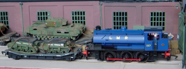
The standard Longmoor Military Railway steam
locomotive livery was royal blue lined red, with red rods and yellow
lettering. By August 1963 Austerity 157 was stored in the Fitters
School in immaculate condition as a ‘show’ loco with valve gear
disconnected and cab controls labelled. It was at one time transported to
exhibitions by road but its eventual fate remains a mystery.
In the picture above LMR 157 is seen shunting an LMS
marked "Lowmac" wagon carrying two sheeted Universal Carriers with a Mark
VII Churchill tank visible on a similar vehicle in the background.
Machine wagons - known in many
railway circles as "Lowmacs" and originally as Loriots on the Great Western
- were built by all the Big Four British railway companies and ranged in
capacity from 12 to 21 to 25 tons.
This would not have presented a problem
for the Universal Carriers but given their full kerb weight of well over 30
tons the Churchills on the Lowmacs must be considered as just metal shells
without engines or other heavy equipment - and also partially dismantled to
fit the railway loading gauge. | |
| |
| |
| |
HIBBERD PLANET FOUR WHEEL PETROL MECHANICAL
LOCOMOTIVE | |
| |
| |
| |
 | |
| |
| |
| |
The origin of the "Planet" locomotive can
be traced back to the Ashford based Kent Construction & Engineering Co. Ltd
which entered the light railway locomotive market after 1918 War when they
purchased a large number of War surplus petrol locomotives and
associated spares.
These locomotives included some built to the American
Baldwin Locomotive Works design but more importantly a number of the
familiar Motor Rail "Simplex" with internal combustion engines set across
the frames. During the next four or five years Kent Construction
brought out a range of locomotives to their own designs which were based
almost entirely on the Motor Rail "Simplex" but which were sold as "Planet"
locomotives. There were both narrow and standard gauge designs with either
petrol, paraffin or alcohol engines which may have incorporated some of the
ex-Government Motor Rail "Simplex" spares, and indeed some appear to have
been rebuilds on Motor Rail underframes. These locomotives were sold by
Honeywill Brothers Ltd of London
The largest Kent Construction "Planet" for standard
gauge track was an 8 ton 40hp machine and from Ashford the manufacture of
"Planet" locomotives was transferred to the wagon building firm of
Stableford & Company, of Coalville, Leicestershire until they went out of
business in 1928 - the cudgel then being picked up by crane makers Bedford
Engineering Ltd until they too failed in 1932!
The Planet name, drawings and goodwill then passed to
fellow Bedford engineering firm James and Frederick Howard and via their
liquidators to internal combustion locomotive builders Hibberd who in turn
moved into the Park Royal Works, London. Hibberd's Planets included
designs with longitudinal as well as transverse engines, many of the small
machines also featuring roller chain final drive although some larger ones
had side-rod drive and resembled Hudswell Clarke products.
In the late 1950s Planet locomotives were distributed
by Thos. Hill (Rotherham) Ltd., but the connection was severed on 31 March
1960 as Hill's considered that their newly introduced "Vanguard" locomotive
would be a competitor.
The manufacture of "Planet" locomotives was moved
again during 1963, when Hibberd became part of the Butterley Group based in
Ripley in Derbyshire and the last Hibberd designed locomotive was built
there in 1968.
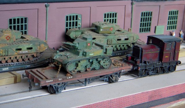
The 4mm scale Roxey Mouldings model seen above is from
the Roxey Mouldings kit and is based on works number 3438 - built in 1950
but strongly resembling pre 1939 designs. The real locomotive -
powered by a Dorman engine was supplied to the National Benzole
refinery at Stanlow and is today preserved on the East Lancashire Railway. | |
| |
| |
| |
 | |
| |
| |
| |
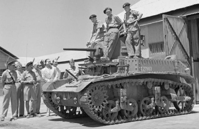
Being shunted by the Hibberd four wheel locomotive is a
four wheeled 20 ton LMS wagon carrying the 12.7 ton load of an M3 light
tank.
With a design lineage stretching back to the M1 combat
car, the M3 was developed at America's Rock Island Arsenal in 1940 and
served with American, British and Soviet forces during World War II.
Upgraded with thicker armour, modified suspension and a new gun recoil
system from the preceding Light Tank M2, the M3 was in production from March
1941 to October 1943.
However, design disadvantages included the transmission
shaft from the 250 bhp Continental 7 cylinder radial engine at the rear to
the driving sprockets at the front passing through the fighting compartment
and the engine itself needing to be mounted high up on the tank, raising its
centre of gravity. The 37mm M5 gun fitted to the M3 also proved
problematic as it lacked the range of guns fitted to opposing German tanks.
The British army in North Africa was the first
organisation to put the M3 into combat. Officially known as the Stuart
- after American Civil War General J.E.B. Stuart - the rivetted-turret
version of the M3 supplied to Britain under Lend-Lease was more commonly
known as the Honey after a tank driver remarked "She's a honey".
Although mechanically reliable, the Honey relied on
speed to hit opposing Panzers and move away quickly - which in turn
highlighted its lack of range. In the highly mobile warfare of North
Africa, this often led to Honeys moving too far ahead of their supply
columns and becoming stranded.
As a result, Honeys were later kept out of
tank-on-tank battles and reserved for reconnaissance and command duties, a
number of "Stuart Recces" having their turrets removed to save weight and so
boost performance and range. The Stuart Kangaroo also developed the M3
hull as an armoured personnel carrier.
In the same way, the American operated M3A1s with
welded turrets and five machine guns as secondary armament that landed with
Operation Torch in November 1942 did not fare well against the Afrika Korps
armour ranged against it in the Battle of Kasserine Pass in February 1943.
As a result, the US Army disbanded its light tank battalions and and
attached one company of light tanks to three of M4 Sherman medium tanks in a
battalion, the M3A1s being used for scouting missions.
M3s were also Lend-Leased to the USSR where the Red
Army considered it undergunned, underarmoured, and likely to catch fire.
This was in part due to the Continental radial engine - originally designed
for aircraft - running on high octane fuel rather than the diesel used in
most Soviet tanks. The narrow tracks were highly unsuited to operation
in winter conditions, as they resulted in high ground pressures under which
the tank sank into the snow.
Although a relative failure on the Russian Steppes,
American M3s proved much more suited to the poor roads and steep terrain of
jungle warfare against the Imperial Japanese Army which, because priority
had been given to equipping Imperial Japanese Navy ships for war
across the Pacific, lacked both modern tanks and anti-tank weapons.
The first U.S. tank versus tank combat to occur in
World War II began on 22 December 1941, when a
platoon of five M3s engaged the Imperial Japanese
Army 4th Tank
Regiment's Type 95 Ha-Go light tanks north of Damortis
in the Phillipines. Later in the War, American M4 Shermans were able to
outnumber and outclass the Japanese Type 97 Chi-Ha medium tanks although
both were less suited to jungle combat.
The M3 was later replaced by the M5 light tank with a
sloping glacis plate to the front hull and twin Cadillac V-8 automobile
engines with twin Hydra-matic transmissions replacing the single Continental
radial. In turn, this was replaced by the M24 Chaffee which went on to
serve in the Korean War, although the M3 went on to feature in a number of
conflicts after 1945 and was not replaced in South America until the 1990s. | |
| |
| |
| |
ON THE ROAD | |
| |
| |
| |
WILLYS JEEP | |
|
| |
| |
 | |
| | | |
| |
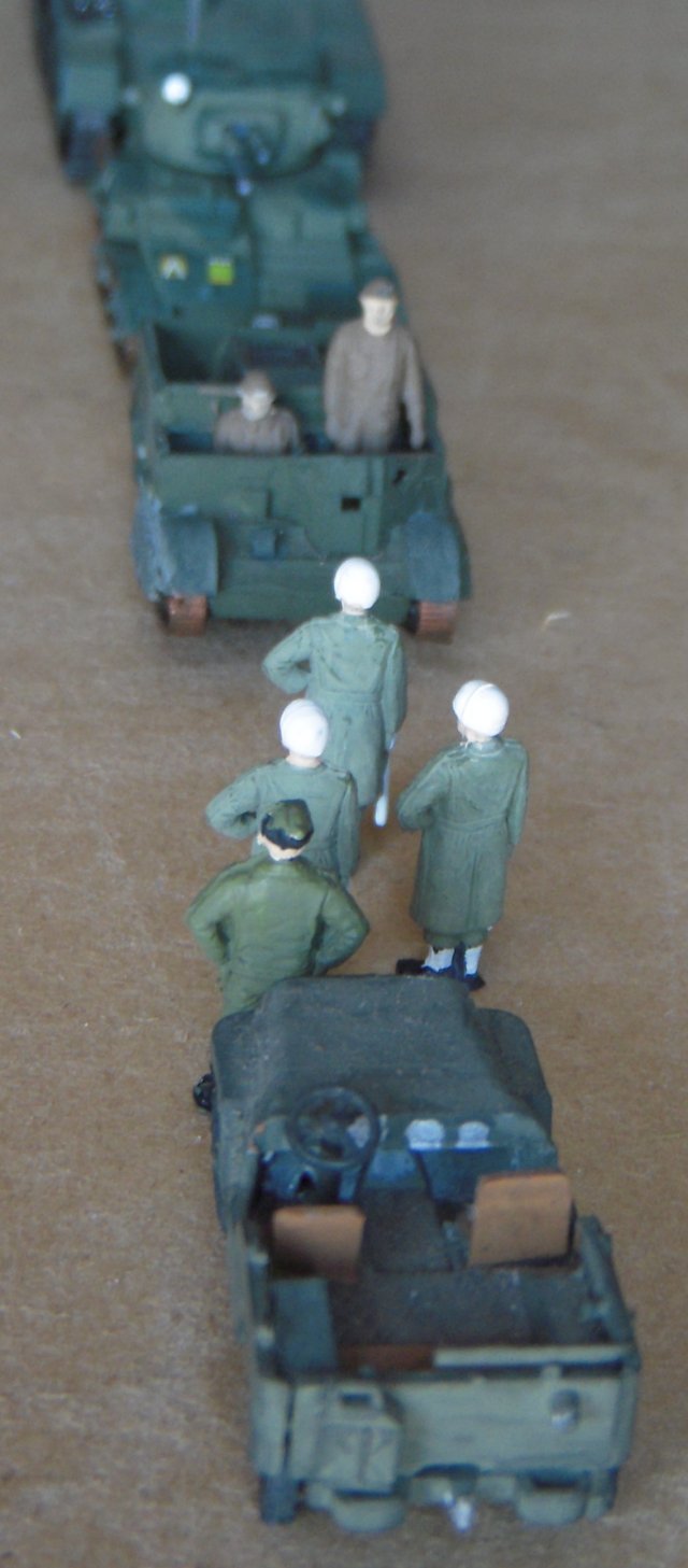
The famous American war correspondent Ernie Pyle called
the Jeep, along with the Coleman GI Pocket Stove, "the two most important
pieces of noncombat equipment ever developed." and together Willys-Overland
and Ford produced 640 000 Jeeps by 1945 which accounted for approximately
18% of all the wheeled military vehicles built in the U.S. during the war.
Nearly 30% of all Jeep production was supplied to
Great Britain and the USSR and Jeeps were also used by every service of the
US military. An average of 145 were supplied to every Army infantry
regiment. Jeeps were used for many purposes including cable laying, saw
milling, as firefighting pumpers, field ambulances,
tractors and, with suitable
wheels, would even run on railway tracks.
Hailed as a masterpiece
of functionalist design, the Jeep - ultimately embracing a term for a small
new vehicle dating back to 1914 - began as the four wheel drive Bantam
Reconnaissance Car conceived by Detroit based designer Karl Probst in three
days in July 1940. Much of the vehicle comprised off-the-shelf
automobile parts and the overall design impressed the US Army, although
production was also spread to Willys-Overland and Ford as the military felt
that the American Bantam was too small a company to make all the units
needed.
Further development led
to Ford adding the distinctive pressed metal vertical-slot radiator while
Willys-Overland Chief Engineer Delmar "Barney" Roos reduced the weight to a
specification for 1 275 lb (578 Kg) including oil and water but was still
able to include the heavy but powerful Willys "Go Devil" engine.
Toledo, Ohio built Willys Jeeps were known as model MBs while Ford produced
4x4s were designated model GPW, G standing for Government, P for 80"
wheelbase and W for Willys engine. | |
| | |
| |
UNIVERSAL CARRIER | |
|
| |
| |
 | |
| | |
| |
Like the White half-tracks
pictured behind it, the Universal Carrier was made famous to a post War
generation by the 1/76 scale Airfix kit on display but could already claim
to be the most produced armoured fighting vehicle in history with 113 000
built in Britain and abroad from 1934 to 1960. The engine was placed along
the centre line of the vehicle ahead of a final drive to the tracks, leaving
room on either side for passengers or supplies.
In earlier versions, the commander's position
next to the driver jutted forward allowing him to fire a Bren light machine
gun through a slit in the armour - giving rise to the popular but incorrect
nomenclature of Bren Gun Carrier. Indeed, a number of varying versions
appeared before the standard "Universal" format was agreed in 1940.
Prior to 1940, the Carden Loyd tankette-derived
tracked carriers were built by Aveling and Porter, Bedford, Ford, Morris,
Sentinel Wagon Works and Thorneycroft with true Universal Carriers appearing
from Aveling-Barford, Ford, Sentinel and Wolseley Motors | |
|
| |
| |
SCAMMELL PIONEER TANK TRANSPORTER WITH VALENTINE
III
TANK | |
| | |
| |
 | |
| |
| |
| |
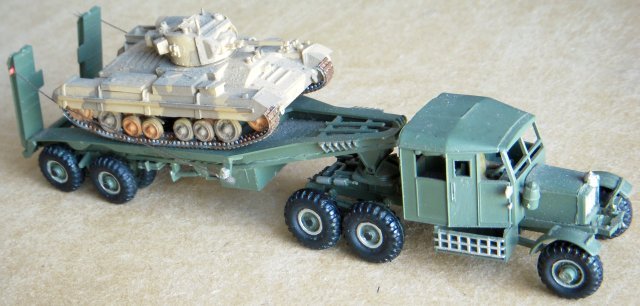
The Scammell Pioneer was
developed in the late 1920s specifically for off road use. Similar vehicles
were then being tested for use in the colonies where surfaced roads were
scarce. The requirement matched that for military vehicles and the British
army obtained a 20 ton tank recovery transporter from the Scammell Company
in 1932. It was later followed by other Pioneers, gun tractors, more tank
transporters and heavy breakdown tractors.
With a freewheeling front axle and two powered
rear axles, the Scammell Pioneer was fitted with a six speed gear box and
vertical spindle worm drive power take off for the loading winch. Both of
these were powered by a 6 cylinder Gardner diesel engine producing 112 bhp
at 1750 rpm.
However, the
essence of the Scammell's off road performance was its unique suspension
system for the rear wheels: mounted, two per side, on a metal casing
containing a gear train. Each casing was pivoted at its centre allowing the
two wheels to drive at a considerable angle from that of the vehicle's
chassis. One rear axle transmitted power to the two gear trains.
The front
unpowered axle was fitted with three attachment points, one at each end of
the axle and the third, by means of an 'A' frame, under the cab. A single
centrally pivoted transverse spring provided the suspension for this axle,
with the result that it could rise and fall to a greater distance from the
chassis than is possible in the case of the more common arrangement with a
spring on each side.
The slow revving
Gardner diesel engine and unusual suspension enabled the vehicle to haul
prodigious weights, though at relatively low speeds, over very rough ground.
The initial tank transporter
(with a Scammell petrol engine) was extensively used for pre-war training in
tank recovery. By the outbreak of World War 2, a small number of
production transporters became available. The first four still used the same
style of transporter semi-trailer with removable rear wheels but these were
soon superseded by, first a 30 ton, and then a 20 ton semi-trailer with
fixed wheels and hinged rear ramps. About 500 were built before the end of
World War 2.
The Pioneers were
all fitted with a chassis winch which, in the case of transporters, enabled
unserviceable tanks to be winched on to the trailer. To provide recovery
crew space behind the driver's cab the chassis of the tank transporter
tractor was longer than those of the gun tractors and breakdown tractors.
The semi-trailers were permanently coupled, that is, not designed to be
easily unhooked like most commercial semi-trailers. Tractors for the 30 ton
semi-trailers were fitted with 1500 x 20 inch tyres at the rear and 1350 x
20 inch tyres at the front. The other Pioneers used 1350 x 20 inch tyres all
round.
The Scammell
transporters made excellent recovery vehicles but had limitations. When used
on roads in the UK during World War 2, loaded with many of the US built
tanks, they were too high to pass under some bridges. In consequence, soon
after the War most of the semi-trailers were sold off for scrap, but the
tractor units were fitted with ballast bodies and used to tow normal
trailers. Some of these survived to be restored in private hands to their
original specification. Only one is known to exist complete with an original
semi-trailer. | |
| |
| |
| |
 | |
| |
| |
| |
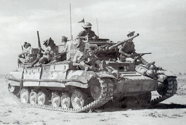
More than 8 000 Valentines were produced
in 11 marks plus various purpose-built variants, accounting for
approximately a quarter of wartime British tank production.
Various explanations have been made for the name
Valentine, including plan submission to the War Office on Valentine's Day
1938, prototype delivery on February 14 1940, the middle name of tank
designer Sir John V. Carden, an acronym for Vickers Armstrong Limited
Elswick and Newcastle upon Tyne, or just an in-house code word used by
Vickers.
Whichever the case, the Valentine design was an
attempt to create an infantry tank with appropriate armour using existing
cruiser tank technology as a basis - resulting in an armoured fighting
vehicle that would be easier, cheaper and faster to produce than the
existing Matilda II.
After so many of the British army's tanks had been
abandoned at Dunkirk in May 1940, the Valentine was rushed into production
despite misgivings about its turret being armed with only a two pounder gun
and manned by only two soldiers - the commander having to double as gun
loader to his gunner.
As well as the 2 515 vehicles produced by Vickers
Armstrong directly, 2 135 were built by the Metropolitan Carriage and Wagon
Company and 2 205 by Birmingham Railway Carriage and Wagon Works.
The Canadian Pacific Railroad's Angus workshops in Montreal also built 1 420
Valentines with General Motors "Detroit" diesel engines, which later
replaced the original petrol engines in later marks of British built
Valentines.
Combining British and Canadian output, the Valentine
was the most-produced British designed tank of World War II and also
represented the British Commonwealth's main Lend-Lease export to the USSR.
In Soviet service the Valentine was
used from the
Battle of Moscow until the end of the war. Although
criticized for its low speed and weak gun, the Valentine was
liked due to its small size, reliability, and generally good
armour protection. In the same way, the Valentine was
regarded as reliable and well armed - and faster than the Cruiser II - in
North Africa where its low profile made it easy to hide "hull down" in a
rolling desert landscape.
The restrictions that the two-man turret
placed on the commander, made more so if they were a troop commander and responsible for directing the
actions of two other tanks besides their own, were addressed
by enlarging the turret for the Mark III so that a dedicated
loader for the main armament could be carried. The turret
ring diameter was not changed so the extra space was found
by moving the gun mounting forward in an extended front
plate and increasing the bulge in the rear of the turret.
This cost a weight increase of half a ton on the 2.5 ton
two-man turret. Similarly, the first Valentines used
the No. 11 Wireless with tannoy for the crew while later variants had the No. 19 Wireless which included crew
communications with long and short range networks.
However, Mark III Valentines equipped with the
superior but larger 6 pounder gun - such as the one modelled - reverted to a
two man turret although by the time that these and later Valentines fitted
with 75mm guns were available in quantity the Valentine design had been
overtaken by American built Shermans and later marks of British Churchill
tanks.
Despite being almost extinct in the
European theatre of operations by 1944, Valentines regunned
with 3" howitzers from Australian Matilda close support
tanks continued to operate in the Pacific with the 3rd New
Zealand Division. In fact New Zealand retained its
Valentines until 1955 while one turretless Valentine which
had been used as a tractor in a quarry was re-activated with
improvised armour and a Bren gun by Greek militiamen in
Cyprus in the early 1960s.
| |
|
| |
| |
BISHOP SELF PROPELLED GUN | |
|
| |
| |
 | |
| | |
| |
Although Vickers Armstrong had examined the possibility
of creating a simple tank destroyer with a 6 pounder field gun on its field
carriage mounted on a Valentine hull, this 1942 experiment did not reach the
production stage as Valentines began being fitted with 6 pounder guns in
their existing turrets. However, June 1941 had
already seen the Birmingham Railway Carriage and Wagon Company entrusted
with developing a self propelled 25 pounder howitzer to cope with the highly
mobile nature of mechanised warfare in the North African desert in which the
Afrika Korps was also using self propelled guns. The prototype of
"Ordnance QF 25-pdr on Carrier Valentine 25-pdr Mk 1" - universally known
as "Bishop" - was ready for trials in August
1941 with 100 units ordered in November that year.
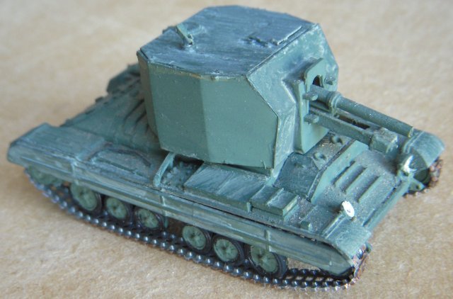
The Bishop was based on the Valentine II hull,
with the turret replaced by a fixed boxy superstructure with
large rear doors -opened when firing to give the crew more room
- into which the 25-pounder gun-howitzer was fitted. As a
consequence, the vehicle had very high silhouette and a maximum
gun elevation of 15 degrees, lowering the range
considerably to about 6,400 yards (5,900 m) - about half that of
the gun on its wheeled carriage. Maximum gun depression was
5 degrees, traverse was
8 degrees and the Bishop could
also carry a Bren light machine gun. By July 1942 80
Bishops had been built, and as the last
20 were being built an order for a
further 50 was placed, with an
option for a further 200 but the
tender was abandoned in favour of the American
M7 Priest 105mm self propelled gun and the British 25 pounder
Sexton.
The Bishop first saw action during the
Second Battle of El Alamein in October and November 1942 North Africa and remained in service
during the early part of the Italian Campaign. However, due to its
limitations and slow speed, the Bishop was poorly received. To gain
elevation, crews would build large ramps out of the earth and run the Bishop
onto them, tilting the vehicle back to increase the range of the gun.
| |
|
| |
| |
CRUSADER ANTI-AIRCRAFT VARIANTS | |
|
|
| |
|
|
 | |
|
|
| |
| |
In 1938, Lord Nuffield's personal company
Nuffield Mechanizations and Aero Limited produced their
A15 Crusader design for a heavy cruiser tank based on the
American Christie suspension widely adopted in the Soviet
Union. This was ordered off the drawing board with
Nuffield's own V-12 Liberty engine and entered production in
1940.Unlike earlier "Christie cruisers" (A13, Marks III and IV
and the Mark V Covenanter) that were built with 4 road
wheels, Crusader had five road wheels each side to improve
weight distribution in a tank that weighed almost 20 tons
instead of the 14 tons of the previous cruisers. The 32 in
(810 mm)-diameter wheels were of pressed steel with solid
rubber tyres. The hull sides were built up of two separated
plates with the suspension arms between them.
In line with the British doctrine of
firing accurately on the move, the main armament, as in other British tanks of the
period, was balanced so the gunner could control its
elevation through a padded shaft against his right shoulder
rather than using a geared mechanism.
Although mechanically unreliable, the
Crusader became one of the most important British tanks of
the North African campaign and its speed helped it
outmanoeuvre its rival Panzer III
When it was understood that there would be delays in the
introduction of successor heavy cruiser tanks — what became
the
Cavalier, Centaur and Cromwell - the Crusader was adapted to use the 6 pounder
gun although this was no match for the Afrika Korps Tiger 1
tanks. Having been replaced by
American made Grant and Sherman medium tanks from October
1943, Crusaders were adapted to a number of roles including
17 pounder gun tractors and self propelled anti-aircraft
guns designed for use in North West
Europe.
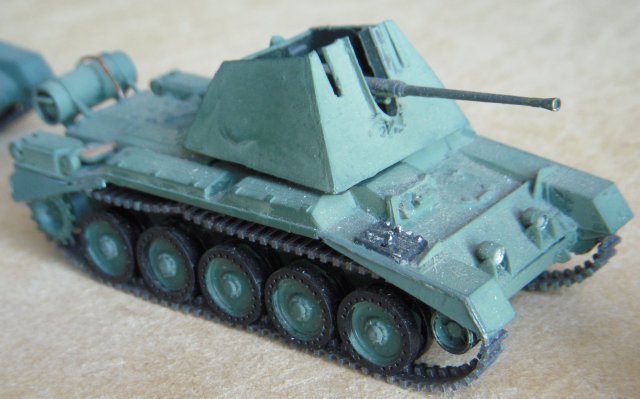
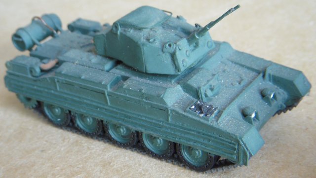
The Crusader III AA Mark 1 seen above
had a single Bofors gun mounted in an open top turret
operated by a gun commander, gun layer, loader, and driver
while the AA Mark II seen below featured twin 20mm Oerlikon
cannon in an enclosed turret
However with the Allied domination of the air they were largely
unneeded and the AA troops were disbanded although a number of these
vehicles were used against ground targets by Polish
Armoured Divisions.
| |
| |
| |
| |
 | |
| |
| |
| |
CHURCHILL 6" GUN CARRIER | |
| |
| |
| |
 | |
| |
| |
| |
The self propelled gun - specifically a motorized or
tracked artillery piece which, unlike a tank, does not have to be in
visual range of its target - became a part of the highly mobile
battlefield tactics which emerged at the start of World War II.
Supporting forces now had to move at the speed of a blitzkrieg and to
exactly the same places, either to lay down a static or creeping barrage
or to offer close support and destroy opposing tanks and fortifications.
SPGs had been crucial in supporting Heinz Guderian's
tanks and infantry in the invasions of Poland and France and by
September 1941 there was an urgent need for self propelled guns to
defend Britain itself and also to support the 8th Army in North Africa.
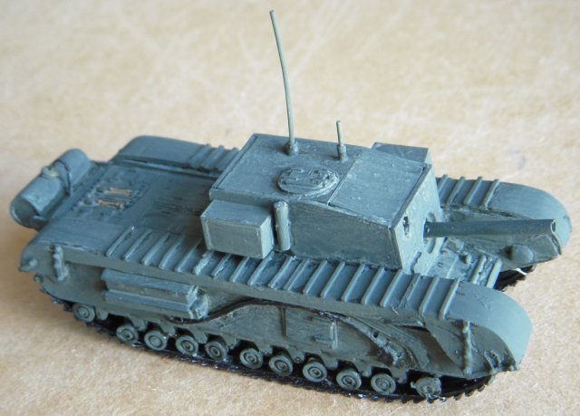
Among the projects approved by the Tank Board was
the application of otherwise obsolete 3" anti aircraft guns on top
of a Churchill hull with a ball mounting inside a fixed 3.5" thick
armoured superstructure. 100 units were ordered, but this was cut
down to 24 in February 1942 and none of them saw active duty. | |
| |
| |
| |
CHURCHILL II | |
| |
| |
| |
 | |
| |
| |
| |
Initially specified prior to the
outbreak of the Second World War the British Army General Staff
designation A20 was to be the replacement for the Matilda and
Valentine infantry tanks. In accordance
with British Infantry Tank doctrine and based on the expected needs of
World War I style
trench warfare, the tank was required
to be capable of navigating shell-.cratered ground, demolishing infantry
obstacles (such as
barbed wire) and attacking fixed enemy
defences. For these purposes, great speed and heavy armament was not
required
The task of design and construction of the A20 was
given to Belfast based shipbuilders
Harland and Wolff who completed four
prototypes by June 1940. The vehicle was armed with two
2-pounder guns each located in a side
sponson and plans existed for an
additional third gun in a central turret. Indeed one of the
Harland and Wolff prototypes was built
with a Matilda turret and the Ulster firm was also responsible for the
side escape hatches which featured on all marks of Churchill.
Even by this point the sponson idea had fallen out
in favour of turret and hull mounted guns. The A20 designs were
short-lived however, as at roughly the same time
the emergency evacuation of the
British Expeditionary Force from
Dunkirk occurred. With
France conquered, the scenario of
trench warfare in Northern Europe was no longer applicable and the
design was revised by Dr. H.E. Merritt, director of Tank Design at
Woolwich Arsenal, based on the combat witnessed in
Poland and France. These new
specifications, for the A22 or Infantry Tank Mark IV, were given to
Vauxhall in June 1940.
With German invasion looking imminent and the
United Kingdom having lost most of its military vehicles in the
evacuation from France, the
War Office specified that the A22 must
begin production within the year. By July 1940 the design was complete
and by December of that year the first prototypes were completed; it was
in June 1941, almost exactly a year as specified, that the first
Churchill tanks began rolling off the production line.
The hull of the Churchill tank was made up of
simple flat plates initially bolted but later welded together. It was
split into four compartments: the drivers position at the front, then
the fighting compartment including the turret, the engine compartment
and then finally the gearbox compartment.
The suspension was fitted under the two large
"panniers" on either side of the hull - the track running over the top.
There were eleven bogies either side, each carrying two 10-inch wheels.
Only nine of the bogies normally took the vehicle weight, the front
coming into play when the vehicle nosed into the ground or against an
obstacle, the rear acting in part as a track tensioner. Due to the
number of wheels, the tank could survive losing several without much in
the way of adverse affects as well as traversing steeper terrain
obstacles. As the tracks ran around the panniers, escape hatches in the
side could be incorporated into the design. These were retained
throughout the revisions of the Churchill and were of particularly use
when the Churchill was adopted as an armoured recovery vehicle.
The Vauxhall designed twin engines were connected
through a common crankshaft feeding a regenerative transmission steered
by a tiller bar rather than levers or steering wheel. The Churchill was
also the first tank to utilize the
Merritt-Brown gear-box, which allowed
the tank to be steered by changing the relative speeds of the two
tracks; this effect was more pronounced as the gears were lowered,
allowing the tank to fully turn on its own axis while in neutral.
Each tank was delivered with a document from the
manufacturer which stated that it had great confidence in the
fundamental design of the tank but that the model had been put into
production without time for proper honing and that improvements would be
made in time:
"All those things which we know are not as they
should be will be put right....Fighting vehicles are urgently required,
and instructions have been received to proceed with the vehicle as it is
rather than hold up production"
This hasty development had not come without cost
though, as there had been little in the way of testing and the Churchill
was plagued with mechanical faults. Most apparent was the Churchill's
underpowered and unreliable engine, a situation made far worse by the
engine's lack of accessibility.
Another serious shortcoming of the tank was the 2
pounder 40 millimetre gun in its cast, round turret fitted with a
Vickers Tank Periscope MK IV. This relatively weak gun was augmented by
the addition of a 3 inch
howitzer in the hull ( or the turret in
the case of the Mk IICS ) to deliver a high explosive shell - albeit not
on howitzer type trajectories.. This enabled the tank to deliver a
useful HE round while retaining the antitank capabilities of the
2-pounder. However, like other multi-gun tanks, such as the French Char
B, it was limited by a poor fire arc. The entire tank had to be turned
to aim of the hull gun. The Mk II dispensed with the howitzer and
replaced it with a bow machine gun | |
| |
| |
| |
CHURCHILL ARMOURED
VEHICLE ROYAL ENGINEERS | |
|
| |
|
 | |
|
| |
|
The
Dieppe raid of 1942 failed with heavy losses of both armour and infantry
because
tanks
were unable to penetrate inland. To overcome or destroy obstacles
during future landings,
J.J.Donovan
of the
Royal Canadian Engineers suggested a tank that could launch a small box
girder as a bridge or a ramp and the Churchill Mark IV was chosen for
this project due to its roomy hull with side doors for loading stores
and equipment.
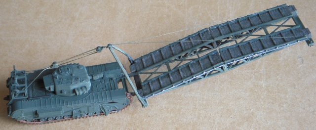
The
prototype Churchill Armoured Vehicle Royal Engineers was ready by
December 1942 with a girder that could span a 30’ gap or allow a 14’
wall to be mounted and a
Petard
spigot mortar added to the modified turret
in February 1943. The Petard could throw a 40 lb projectile containing
a 26lb charge up to 230 yards to destroy concrete obstacles.
| |
|
| |
|
CHURCHILL AMRCD | |
|
| |
|
 | |
|
| |
|
Later
Churchill IIIs sported
75mm guns, as did the Mark VII seen above on the Lowmac railway wagon.
With
a
wider
and better armoured hull and completely new turret,
the 40 ton so-called Heavy Churchill was introduced for the Normandy
landings in June 1944 but was slower than earlier marks as the engine
had not been upgraded to provide more power. Ultimately, the Churchill
was held back by the size of its turret, which could not take a gun
bigger than 75mm and so did not allow it to hit back effectively against
better armed panzers even if it could absorb much of their fire.
Despite unexpected successes in the mountainous terrain of Korea, gun
Churchills left the British Army in 1952 although more specialist
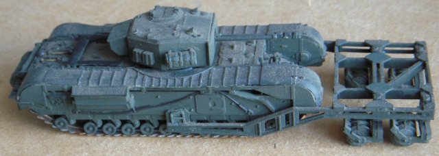
versions continued into the 1970s. Among them – and built by Gloucester
RCW - was the
AMRCD
(Anti-Mine Reconnaissance Castor Device) developed in 1943 but never
used operationally. Like the flail version of the Sherman, this was
designed to clear a path through minefields by exploding any devices
ahead of the tank and is based on a Mark
IV chassis. | |
|
| |
|
VICKERS MARK VI C LIGHT TANK | |
|
| |
|
 | |
|
| |
|
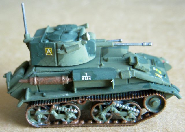
The Tank, Light, Mk VI was the sixth in
the line of similar vehicles built by Vickers-Armstrong for
the British Army, having a degree of standardization with
their previous five models. The Mark VI turret, which had
been expanded in the Mark V to allow a three-man crew to
operate the tank, was further expanded to give room in its
rear for a wireless set. The weight of the tank was
increased to 10 800 pounds (4 900 kg) - which although
heavier than previous models actually improved its handling
characteristics - and an 88 horsepower (66 kW) engine was
added to the model to increase its maximum speed to 35 miles
per hour (56 km/h).The Mark VI
also had the Horstmann coil-spring suspension system which
was found to be durable and reliable, although the fact that
the tank was short in relation to its width and that it
pitched violently on rough ground made accurate gunnery
whilst moving exceptionally difficult.
Operated by a driver, gunner and
commander / wireless operator, the Mark VI was armoured
thickly enough to withstand rifle and machine gun fire and
armament comprised one .303 and one 0.5" Vickers
machine gun.
Production of the Mk VI began in 1936
and ended in 1940 with 1 682 Mark VI tanks having been
built. The final Mk VI C - as modelled above - had the
commanders cupola removed and had wider bogies and three
carburettors to improve engine performance. It
was also more powerfully armed than the other models with
co-axial 15-millimetre (0.59 in) and 7.92-millimetre (0.312
in) Besa machine guns.
Like many of its predecessors, the Mark VI was
used by the British Army to perform imperial policing duties in India
and other colonies, a role for which it and the other Vickers-Armstrongs
light tanks were found to be well suited. When the British
government began its rearmament process in 1937, the Mk VI was the only
tank with which the War Office was ready to proceed with manufacturing.
As a result of this, when the Second World War began in September 1939,
the vast majority of the tanks available to the British Army were Mk VIs | |
|
| |
|
MATILDA II | |
|
| |
|
 | |
|
| |
| |
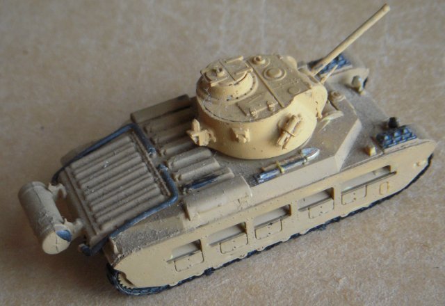
Due to its heavy armour the Type A12 Matilda II was
the only British tank to serve throughout World War II, surviving into
late 1945 with Australian forces due to the Japanese army's lack of
anti-tank guns comparable to the German 75mm PAK 40 and 88mm which the
Matilda had encountered in North Africa in 1940-1942. The first of 2 987
Matilda IIs built - armed with a QF 40mm 2 pounder gun but always
lacking a suitable high explosive shell - were completed by the
Vulcan Foundry from 1937,
other examples being outshopped from such famous railway organisations
as John Fowler of Leeds, Ruston & Hornsby, North British Locomotive in
Glasgow and the Horwich works of the LMS as well as Harland & Wolff in
Belfast. | |
| | | |
| |
MATILDA II CRANE TANK AND MATILDA II CANAL
DEFENCE LIGHT | |
| | | |
| |
 | |
| | | |
| |
The deliberately misleading name of Canal
Defence Light was given to the use of a powerful carbon arc
searchlight mounted in a tank turret during night-time
attacks, when the light would allow enemy positions to be
targeted. A secondary use of the light would be
as a strobe to dazzle and disorient enemy troops, making it
harder for them to return fire accurately.
The idea is credited to a Greek
citizen, A V M Mitzakis, who devised the system in 1937
although the British War Office only applied a prototype
cylindrical turret - carrying a 13 million candlepower
searchlight and a Besa machine gun - to a Matilda II tank in
1940.
The searchlight operator who had the
task of changing the light's carbon electrodes when they
burned out and working the shutter that could flash the beam
on and off up to twice a second was also the machine gunner
while the driver also operated the radio set.
The light emerged from a vertical slit
that measured just 2" by 24" which reduced the chance of
battle damage to the optical system. The beam diverged at
19° horizontally and 1.9° vertically, forming a pool of
light of around 34 by 340 yards (31 m × 311 m) at a distance
of 1,000 yards (910 m). The turret could rotate 360° and the
light beam could be elevated or depressed by 10° from the
horizontal.
Blue and amber filters allowed the
light to be coloured as well as white. It was found the blue
light caused the CDL tank to appear to be at a greater
distance while a blue and amber light beams from two CDL
tanks could combine to illuminate a target with white.
Rather than working alone, it was
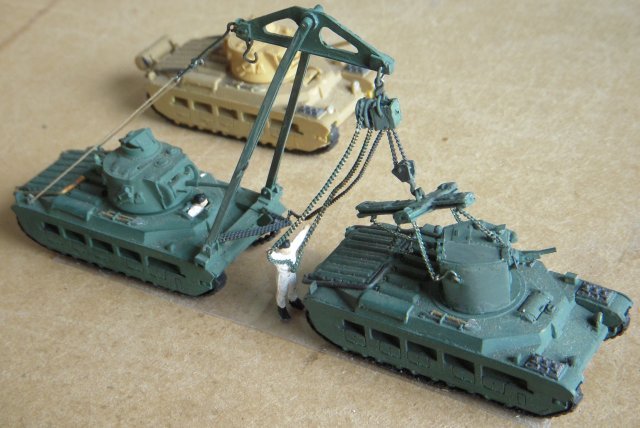
envisaged that CDL Matildas would be embedded in larger
units of gun Matildas, some of which would be equipped with
five ton cranes to rapidly exchange CDL turrets for standard
two pounder gun equipped turrets and vice versa as the
battle situation demanded.
Although the Matilda II was later
replaced as a CDL platform by the faster, roomier and better
armed American made M3 Grant tank, secret tests of the
system at Tighnabruaich in Scotland concluded that Canal
Defence Light was "too uncertain to be depended upon as the
main feature of an invasion".
Indeed, such was the secrecy
surrounding Canal Defence Light that few commanders in the
field ever heard of it or planned to use it for its intended
purpose. However, the adapted tanks were used by US
forces in March 1945 to protect bridges over the Rhine being
threatened by German swimming saboteurs and mines released
upstream of the bridge piers.
The armour of the CDL's made them more
suitable for this task than conventional searchlights as, in
some sectors, the East bank of the river was held by German
forces who subjected the CDL tanks to considerable artillery
and small-arms fire.
Later, the battle moved East and the
CDLs were used to illuminate the bridges for the benefit of
engineers carrying out maintenance until they were replaced
by captured German searchlights.
| |
| | | |
| | |
| | | | |
| | | | |